Why 3.3V?

TTL Logic Levels

A majority of systems we use rely on either 3.3V or 5 V TTL Levels. TTL is an acronym for Transistor-Transistor Logic. For any logic family, there are a number of threshold voltage levels to know. Below is an example for standard 5V TTL levels:

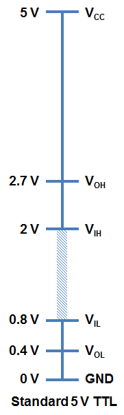
You will notice that the minimum output HIGH voltage (VOH) is 2.7 V. Basically, this means that output voltage of the device driving HIGH will always be at least 2.7 V. The minimum input HIGH voltage (VIH) is 2 V, or basically any voltage that is at least 2 V will be read in as a logic 1 (HIGH) to a TTL device.

You will also notice that there is cushion of 0.7 V between the output of one device and the input of another. This is sometimes referred to as noise margin.

Likewise, the maximum output LOW voltage (VOL) is 0.4 V. This means that a device trying to send out a logic 0 will always be below 0.4 V. The maximum input LOW voltage (VIL) is 0.8 V. So, any input signal that is below 0.8 V will still be considered a logic 0 (LOW) when read into the device.

What happens if you have a voltage that is in between 0.8 V and 2 V? Well, your guess is as good as mine. Honestly, this range of voltages is undefined and results in an invalid state, often referred to as floating. If an output pin on your device is “floating” in this range, there is no certainty with what the signal will result in. It may bounce arbitrarily between HIGH and LOW.

3.3 V CMOS Logic Levels

As technology has advanced, we have created devices that require lower power consumption and run off a lower base voltage (Vcc = 3.3 V instead of 5 V). The fabrication technique is also a bit different for 3.3 V devices that allows a smaller footprint and lower overall system costs.

In order to ensure general compatibility, you will notice that most of the voltage levels are almost all the same as 5 V devices. A 3.3 V device can interface with a 5V device without any additional components. For example, a logic 1 (HIGH) from a 3.3 V device will be at least 2.4 V. This will still be interpreted as a logic 1 (HIGH) to a 5V system because it is above the VIH of 2 V.

A word of caution, however, is when going the other direction and interfacing from a 5 V to a 3.3 V device to ensure that the 3.3 V device is 5 V tolerant. The specification you are interested in is the maximum input voltage. On certain 3.3 V devices, any voltages above 3.6 V will cause permanent damage to the chip. You can use a simple voltage divider (like a 1KΩ and a 2KΩ) to knock down 5 V signals to 3.3 V levels or use one of our logic level shifters.

thanks to sparkfun for this info.

How to break an HDTV

When my 55-inch LED tv went black, I brought it to the basement with the intention that one day I will fix it. A year later, I finally got around to it. This article is about that experience.

Before my tv finally conked out, I would be able to smack the back of it to get it to work. It would work for hours or even days. Then out of nowhere, it would lose the picture. I figured, there was a loose connection somewhere. I removed the back cover to inspect, nothing obvious.

With the help of YOUTUBE sites bigdog and shopjimmy, I was guided towards what the possible problem might be.

Backlights

I learned that my backlights (LEDs) are the probable cause.

Without a backlight, the image produced by the tv would not be visible. To verify, take a flashlight and put it against the screen, you should be able to see an image. Another sign that your LEDs are malfunctioning, After powering the tv on, the backlights will flash on then back off. These are signs that you have backlight LED problems.

LEDS

An LED tv uses strips of LEDS to produce light. The number of LEDs for each TV varies by size. My 55-inch tv has 5 rows of 9 LEDs (see circuit below). Each strip needs 38volts to activate. The circuit that powers the LED strips is integrated within the main power supply board.

Every LED strip is a series circuit. Hence if one LED in that strip is open then the entire strip will not light. If one strip goes out, that will result in the current increasing for the other strips. To prevent damage, your tv shuts down the entire backlight circuit.

Test voltage

Before disassembling, check voltage at the connector. To identify which cable is for the LEDs follow the black cable that routes into the chassis. Also, read the connector labels, My connector reads +Vled and -Vled.

When my circuit is working properly, all +Vled should read 38volts. With 38v at the connector, the LED strip should be illuminated. If it is not, proceed to disassemble the tv to gain access to the LED strips.

If an LED strip is bad, you will measure 38volts when powered on, then the voltage will gradually decrease.

Remove the screen

To access the backlights, you have to separate the front screen from the chassis. Refer to shop jimmy and bigdog, they have lots of videos and tutorials on this topic.

Test LED STRIPS

Now that you have your tv separated, your LED strips are exposed.

There is an invaluable tool available called a LED backlight tester. It allows you to quickly apply voltage to the connector, individual strips or individual LED. It generates the proper voltage to test those components. There are various models available , usually less than $40. I used it to test each strip and narrow down to which one was defective.

With the LEDs illuminated, I pressed and shook the connector. What I found was a loose connection, between two strips. To fix it, I unscrewed and removed the strip from the base, then connected it back, making sure the connection was tight before securing hardware.

See schematic of LED strip in failed state.

Conclusion

Back to the title of the article. “How to break a Television“. Separating and removing the layers of the TV takes, time, patience, and a few special tools. While separating the liquid crystal layer, I cracked it. The professionals use a special suction cup to lift the liquid crystal screen from the stack. I did not buy one, I cut corners and tried to slide the screen, instead of lifting it. No good – CRACK! I fixed the original problem, then created another. Lesson learned.

The moral of my story, troubleshooting and repairing this common TV failure is doable, just take your time, look at a few videos and purchase a few inexpensive tools.

Fix Washing Machine Noise

Sooner or later your washing machine will fail. So either you she’ll out another $700 to replace it or read this blog and spend $50 to replace bearings.

So my washing machine was making a horribly loud noise for several months. I knew there was a problem, but heck, it still cleaned my clothes, so I ignored it.

Problems that are ignored always get worse. So this blog is how to replace my bearings which were the cause of my washing machine noise.

This is my washing machine. The model number is Kenmore 402.49032011. Don’t get too weirded out. Most front loaders irregardless of the brand are build the same. Not identical, but very similar. So changing the bearings will be a similar process no matter what model you have.

This is it. You have to remove the tub from the unit. No if and or buts. If you have no mechanical intelligence I probably would stop reading this and Google a technician.

These are the steps:

– Remove covers

-look at your tub, remove hoses and electrical connectors that prevent it from being removed from unit. Take pics, if needed of every hose clamp and electrical connector.

Next step is to remove the bottom struts. Don’t worry your tub won’t drop. Be sure to leave one end connected to tub. Just remove end connected to cabinet.

Ok. This next step is important. Be sure your tub is free from all hoses, connectors and struts. Your tub should be held by two springs. You will probably need a hand for this. As you lift the weight off of the tub, have someone detach the spring from the cabinet. Now the tub can be removed from the cabinet.

Now that the tub is removed locate the bolts that are around the circumference of the tub. Remove all of them.

Separate the upper half from the lower half. Locate the bearings. They are probably visibly destroyed, maybe the balls are exposed.

Remove seal, with hammer and punch, remove the bearings. Be sure to remove both of them. Clean up dirt and grim as needed.

Critical step…After you order new bearings, they need to be properly installed. Never ever ever hit them on the inner race. They should be hit in on the outer race or find some sort of plate to hit the entire bearing in.

So you have done it. You installed the bearings. To reassemble, just perform the disassembly steps in reverse. Hopefully this blog set you in the right mindset. Of course you should look at YouTube videos of others who have performed the job. I just want to give you the confidence, so you know anyone can do this. Cheers……